LIRO documentation

ABSTRACT
The invention relates to a transport system comprising: a rotatable shaft (1), a plurality of permanent driving magnets (2) fixed to the shaft (1) and having the poles axes phase-shifted by 120º, at least one set of three identical permanent propulsion magnets (4), a movable element (5) provided with two profiled extremities (6) and fixed to the at least one set of propulsion magnets (4), two guide rails (7) each provided with a groove (8) such that each extremity (6) of the movable element (5) is accommodated in a respective groove (8), wherein, on the surfaces of the extremities (6) and on the matching surfaces of the grooves (8) are fixed permanent guide magnets (9; 10) having magnetic poles oriented such that the guide magnets (9) of the extremities (6) are in magnetic repulsion with the guide magnets (10) of the grooves (8).
[001]
The invention relates to a magnetic levitation transport system, more precisely to a transport system comprising a movable element in magnetic levitation.
[002]
The invention also relates to a method of moving a movable element, using the aforementioned transport system.
[003]
Currently, the technology of the rotary-linear transmission and of the magnetic levitation systems is used in various fields, such as the industrial transport or the precision guidance systems.
Most of the existing solutions are based either on purely mechanical mechanisms, or on electromagnetic systems that require a direct power supply and involve several limitations, such as mechanical wear, the need of a permanent electric energy supply or maintenance hardships.
On the other hand, magnetic levitation systems used in Maglev trains require a complex control of the electromagnetic fields and a very expensive specialized infrastructure that is difficult to implement and to operate.
[004]
The technical problem solved by the invention is to obtain a transport system having a simple design, low manufacturing and operating costs and an efficient and accurate movement of the movable element.
[005]
The transport system according to the invention can be used, for example, for fluids (such as water or crude oil) extraction from great depths and bringing said fluids to surface, for the vertical movement of an elevator (residential or industrial), or for the horizontal movement of various loads (such as objects, goods, people, animals, etc.).
[006]
In a preferred embodiment, the transport system according to the invention comprises:
- a shaft supported on bearings provided in a supporting frame fixed to the ground, said shaft being capable to rotate, when driven by a driving means, about a proper longitudinal symmetry axis,
- a plurality of identical permanent driving magnets fixed to the shaft, equally spaced in a row along the shaft, wherein each driving magnet has a magnetic poles axis perpendicular to the longitudinal axis of the shaft, wherein each driving magnet, which is not situated at an end of said row, has its magnetic poles axis phase-shifted by +120º in respect to a magnetic poles axis of the precedent neighbouring driving magnet and phase-shifted by -120º in respect to a magnetic poles axis of the subsequent neighbouring driving magnet,
- at least one set consisting of three identical permanent propulsion magnets, wherein
- the propulsion magnets are each configured as a plate having a flat surface facing the shaft, the flat surfaces of all the propulsion magnets being coplanar,
- the common plane of all the flat surfaces of the propulsion magnets is at a distance ranging from 1 mm to 10 mm in respect to the driving magnets,
- the poles of the propulsion magnets are all arranged in the direction of the longitudinal axis of the shaft in the succeeding order N-S, N-S, N-S,
- a movable element provided with two profiled extremities and fixed to the at least one set of propulsion magnets, such that the propulsion magnets are arranged between the driving magnets and the movable element, wherein, when viewed in a plane perpendicular to the longitudinal axis of the shaft, the movable element, the propulsion magnets and the shaft have a common symmetry axis,
- two guide rails fixed to the supporting frame, symmetrically arranged on one side and the other of the shaft, each rail being provided with a groove and arranged in respect to the movable element such that each extremity of the movable element is accommodated in a respective groove, and the shape of the surface of each groove matches the shape of the surface of the respective extremity, wherein, on the surfaces of the extremities and on the matching surfaces of the grooves are fixed permanent guide magnets having magnetic poles oriented such that the guide magnets of the extremities are in magnetic repulsion with the guide magnets of the grooves.
[007]
In a preferred embodiment of the transport system according to the invention, the driving magnets have an annular shape, are diametrically polarized, are arranged on the outside of the shaft and coaxially with it, and the distance between two consecutive driving magnets is at most 3 mm.
[008]
In a preferred embodiment of the transport system according to the invention,
- the driving magnets have a substantially cylindrical or prismatic bar shape and are fixed inside diametrical through holes provided in the shaft, whose longitudinal axes are each perpendicular to the longitudinal axis of the shaft,
- the base surfaces of the driving magnets are configured to be flush with the lateral surface of the shaft,
- the minimum distance between the contours of two adjacent base surfaces is at most 3 mm.
[009]
In a preferred embodiment, the transport system according to the invention further comprises:
- a first assembly of identical keepers fixed to the supporting frame, wherein the number of keepers is identical to the number of driving magnets, and the keepers are equally spaced in a row such that each keeper faces one respective driving magnet, wherein each keeper comprises:
- a first keeper surface oriented towards the shaft, having a shape matching the surface shape of the driving magnet facing it, and arranged at a distance ranging between 1 mm to 2 mm in respect to said driving magnet,
- a second, flat, keeper surface, opposite the first keeper surface,
wherein the second flat surfaces of all the keepers are coplanar, and the common plane of all the second flat surfaces of the keepers is parallel to and at a distance ranging between 1 mm to 3 mm in respect to the common plane of the flat surfaces of the propulsion magnets.
[010]
In a preferred embodiment of the transport system according to the invention, the movable element is configured as a plate, having a length, measured in the direction of the longitudinal axis of the shaft, smaller than the length the shaft.
[011]
In a preferred embodiment, the transport system according to the invention further comprises a second assembly of keepers fixed to the supporting frame, identical to the first assembly of keepers and arranged diametrically opposite, in respect to the shaft, to the first assembly of keepers, wherein
- the guide rails have each the shape of a closed loop consisting of two straight sections and two curved sections, such that the first curved section connects a first extremity of the first straight section to a first extremity of the second straight section, and the second curved section connects a second extremity of the first straight section to a second extremity of the second straight section,
- the movable element consists of a closed loop conveyor belt comprising a plurality of substantially rectangular individual plates hinged to each other, wherein a respective propulsion magnet is fixed to each one of the individual plates.
[012]
In a preferred embodiment, the transport system according to the invention further comprises a plurality of containers fixed to the movable element such that the movable element is arranged between said containers and the propulsion magnets.
[013]
The method according to the invention, of moving a movable element, comprises the following steps:
a) positioning, in an initial position, the movable element of a transport system according to the invention;
b) driving the shaft, by means of a driving means, in a rotational movement about its longitudinal symmetry axis, causing a movement of the movable element in the direction of the longitudinal axis,
c) halting the rotation movement of the shaft and implicitly halting the movable element when the movable element has reached a desired intermediate or final position.
[014]
Steps b) - c) may be repeated as needed, and in step b) the rotational movement of the shaft may be a clockwise and/or an anti-clockwise one.
[015]
The transport system according to the invention has the following advantages:
- it uses only permanent magnets, being totally independent of external power sources for generating magnetic fields,
- it allows an efficient and accurate movement of the movable element,
- it has low operating and maintenance costs.
[016]
Below are disclosed two non-limiting embodiments of a transport system according to the invention, in connection with figures 1-10, representing:
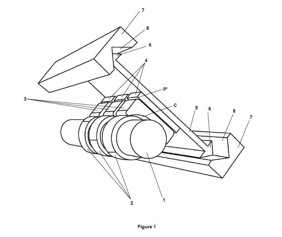
Figure 1: axonometric view of the transport system according to a first embodiment of the invention
Figure 2: "front" view of the system from Figure 1
Figure 3: "top" view of the system from Figure 1
Figures 4, 5: shaft provided with outer driving magnets
Figure 6: shaft provided with inner driving magnets
Figure 7: schematic representation of the poles axes of the driving magnets shown in Figures 4 and 5
Figure 8: axonometric view of the transport system according to a second embodiment of the invention, wherein the movable element is partially displayed
Figure 9: "front" view of the system from Figure 8
Figure 10: axonometric view of the transport system from Figure 8, wherein the movable element is entirely displayed
[017]
Figure 1 schematically shows a first embodiment of the transport system according to the invention. Said system comprises a shaft 1 supported by bearings provided in a supporting frame fixed to the ground. The term "ground" must be interpreted broadly, as it can be assimilated, for example, to a floor, to a platform, to a wall, etc. For simplicity reasons, the bearings and the frame are not shown in Figure 1. The shaft 1 is capable to rotate, when driven by a driving means (not shown in Figure 1), about its proper longitudinal symmetry axis X (shown in Figures 3-6). Said driving means may be, for example, an electric motor or a spindle connected to an electric motor. The length of the shaft 1 substantially corresponds to the desired transport distance.
[018]
Along almost the entire length of the shaft 1 are fixed several identical permanent driving magnets 2, equally spaced in a row.
The driving magnets 2 may all be arranged on the exterior of the shaft 1, as shown in Figures 1-5 and 7-9, in which case they have an annular shape, are diametrically polarized, are coaxial with the shaft 1, and the distance between two consecutive driving magnets 2 is at most 3 mm.
In another embodiment, the driving magnets 2 can all be arranged inside the shaft 1, as shown in Figure 6, in diametrical through holes whose longitudinal axes are perpendicular to the longitudinal axis X of the shaft 1. In this case, the shape of the driving magnets 2 is that of a substantially cylindrical or prismatic bar, wherein the base surfaces are configured to be flush with the lateral surface of the shaft 1. The minimum distance between the contours of two adjacent base surfaces is at most 3 mm.
In both above mentioned cases (driving magnets 2 arranged on the exterior, respectively inside the shaft 1) each driving magnet 2 has its magnetic poles axis perpendicular to the longitudinal axis X of the shaft 1. Additionally, each driving magnet 2, which is not situated at an end of the row, has its magnetic pole axis pi phase-shifted by +120º in respect to the magnetic poles axis pi-1 of the precedent neighbouring driving magnet 2 and phase-shifted by -120º in respect to the magnetic poles axis pi+1 of the subsequent neighbouring driving magnet 2. The schematic representation of the phase-shifted poles axes pi-1, pi, pi+1 is shown in Figure 7.
Specifically, the N (north) pole situated on the pi axis is phase-shifted by +120º in respect to the N pole situated on the pi-1 axis and phase-shifted by -120º in respect to the N pole situated on the pi+1 axis.
[019]
The system shown in Figure 1 further comprises a first assembly of identical keepers 3 fixed to the supporting frame. The keepers 3 are also equally spaced in a row, and their number is identical to the number of driving magnets 2, such that each keeper 3 faces one respective driving magnet 2. Each keeper 3 comprises a first keeper surface C oriented towards the shaft 1, having a shape matching the surface shape of the driving magnet 2 facing it, and a second, flat, keeper surface P (shown in Figure 2), opposite to the first keeper surface C.
The first keeper surface C is arranged at a distance ranging between 1 mm to 2 mm in respect to the driving magnet 2 facing it.
The second flat surfaces P of all the keepers 3 are coplanar.
[020]
The system shown in Figure 1 further comprises at least one set consisting of three identical permanent propulsion magnets 4. The propulsion magnets 4 are each configured as a plate, having a flat surface P' facing the keepers assembly 3, the flat surfaces P' of all the propulsion magnets 4 being coplanar. The common plane of all the flat surfaces P' of the propulsion magnets 4 is parallel to and at a distance ranging from 1 mm to 3 mm in respect to the common plane of the second flat surfaces P of the keepers 3.
The poles of the propulsion magnets 4 are all arranged in the direction of the longitudinal axis X of the shaft 1 in the succeeding order N-S, N-S, N-S, where N and S denote the north pole and the south pole of the magnet, respectively.
[021]
The system shown Figure 1 further comprises a movable element 5, provided with two profiled extremities 6 and fixed to the at least one set of propulsion magnets 4, such that the propulsion magnets 4 are arranged between the keepers assembly 3 and the movable element 5. When viewed in a plane perpendicular to the longitudinal axis X, the movable element 5, the propulsion magnets 4, the keepers 3 and the shaft 1 have a common symmetry axis.
The keepers 3 are made, for example, of ferrite, and have the purpose of guiding and amplifying the magnetic fields generated by the driving magnets 2 towards the movable element 5.
For applications that do not require very intense magnetic fields (where it is not necessary for the movable element 5 to move at high speed and/or to transport heavy loads), the keepers 3 may be absent from the transport system. In such a case, the common plane of all the flat surfaces P' of the propulsion magnets 4 will be arranged at a distance ranging between 1 mm to 3 mm in respect to the driving magnets 2.
[022]
The system shown in Figure 1 further comprises two parallel guide rails 7, fixed to the supporting frame, symmetrically arranged on one side and the other of the shaft 1, each rail 7 being provided with a groove 8 and arranged in respect to the movable element 5 such that each extremity 6 of the movable element 5 is accommodated in a respective groove 8, and the shape of the surface of each groove 8 matches the shape of the surface of the respective extremity 6.
The length of the movable element 5, measured in the direction of the longitudinal axis X, is substantially smaller than the length the shaft 1. Basically, the movable element 5 is a platform trolley capable to move in the direction of the axis X.
On the surfaces of the extremities 6 and on the matching surfaces of the grooves 8, which are in fact arranged face to face, are fixed permanent guide magnets 9, 10 (shown in Figure 2) having magnetic poles oriented such that the guide magnets 9 of the extremities 6 are in magnetic repulsion with the guide magnets 10 of the grooves 8. By virtue of this arrangement, the extremities 6 never come into contact with the grooves 8, thus permanently maintaining the movable element 5 in a levitation state.
[023]
Fixing the permanent magnets (driving 2, propulsion 4 and guide 9, 10) to the shaft 1, to the movable element 5, to the extremities 6 and to the grooves 8 is accomplished by any known suitable means, for example with screws or/and with adhesives.
[024]
Depending on the applications for which they are assigned, the permanent magnets may be manufactured from various known materials, such as:
- Neodymium-Iron-Boron alloy, which provides the highest magnetic field intensity (relative to the volume of the magnet) and can be used at temperatures below 100 ºC and in low corrosive environments;
- Samarium-Cobalt alloy, which is more fragile and provides a lower magnetic field intensity compared to the Neodymium-Iron-Boron alloy, but which can be used at temperatures up to 300 ºC and in corrosive environments;
- Aluminium-Nickel-Cobalt alloy, which provides the lowest magnetic field intensity (compared to the above mentioned alloys), but which can be used at temperatures up to 500 ºC.
[025]
Non-limiting examples of dimensions for the annular shape driving magnets 2 are: the inner diameter ranges between 2 cm to 5 cm, the outer diameter ranges between 3 cm to 6 cm.
[026]
The preferred distance between a driving magnet 2 and a keeper 3 is 1 mm, which ensures an optimal magnetic efficiency while ensuring the avoidance of the unwanted accidental situation wherein the keepers 3 come into contact with the driving magnets 2.
[027]
The distance between a propulsion magnet 4 and a keeper 3 ranges between 1 mm to 3 mm.
[028]
The operation of the transport system shown in Figure 1 will be described hereafter. Firstly, it is deemed that the movable element 5 is in an initial position. By means of the driving means (for example a motor) the shaft 1 is driven in a rotational movement about its proper longitudinal axis X. Each driving magnet 2 will generate an own rotating magnetic field, and due to the fact that the driving magnets 2 have their poles axes pi-1, pi, pi+1 phase-shifted by 120º, the individual rotating magnetic fields will generate together a progressive (also called sliding) magnetic field moving in the direction of the axis X. The interaction of the progressive magnetic field with the magnetic field generated by the propulsion magnets 4 generates a magnetic force having a component oriented in the direction of the axis X, that determines the moving of the propulsion magnets 4 and implicitly of the movable element 5 in the direction of the axis X.
Halting the movable element 5 upon reaching a desired position (which may be an intermediate or a final one), is achieved by halting the driving of the shaft 1.
The sense of movement of the movable element 5 in the direction of the X axis is determined by the sense of rotation (clockwise or counter clockwise) of the shaft 1.
The load to be transported along the axis X can be laid, as appropriate, either directly on the upper surface of the movable element 5 or in containers fixed to the movable element 5.
[029]
Figure 2 shows a "front" view of the system from Figure 1, wherein the references P (the flat surface of the keeper 3), 9 (the guide magnets of the extremities 6) and 10 (the guide magnets of the grooves 7) are also specified.
[030]
Figure 3 shows a "top" view of the system from Figure 1, wherein reference X (the longitudinal axis of the shaft 1) is also specified. In this figure, strictly for a better understanding of the system configuration, it was not represented the keeper 3 that should be above one of the driving magnets 2 (in reality, said keeper is present).
[031]
Figures 4 and 5 show a shaft 1 provided with outer driving magnets 2. The only difference between the two figures is that Figure 5 indicates the arrangement of the magnetic poles of each driving magnet 2, thus providing a clear view of the above-mentioned 120° phase-shift of the axes pi-1, pi, pi+1.
[032]
Figure 6 shows a shaft 1 provided with inner driving magnets 2.
[033]
Figure 7 shows a "profile" view of the shaft 1 from Figures 4 and 5, showing the axes pi-1, pi, pi+1 of the poles of the driving magnets 2 and their 120° phase-shift angles.
[034]
Figure 8 schematically shows, in an axonometric view, a second embodiment of the transport system according to the invention. Although it has some constructive differences, the second embodiment works exactly according to the same principle as the first embodiment.
[035]
According to the second embodiment, the two guide rails 7 have each the shape of a closed loop consisting of two parallel straight sections and two curved sections.
Furthermore, the movable element 5 consists of a closed loop conveyor belt comprising a plurality of substantially rectangular individual plates 5.1, 5.2, 5.3 hinged to each other, wherein a respective propulsion magnet 4 is fixed to each one of the individual plates 5.1, 5.2, 5.3.
Additionally, the system according to the second embodiment comprises a second assembly of keepers 3' (exclusively visible in Figure 9) fixed to the supporting frame, wherein the second assembly of keepers 3' is identical to the first assembly of keepers 3 and is arranged diametrically opposite, in respect to the shaft 1, to the first assembly of keepers 3.
[036]
Figure 8, strictly for a better understanding of the second embodiment design, shows only three individual plates 5.1, 5.2, 5.3 of the movable element 5, both at the top side and at the bottom side, in order for the other elements of the system to remain visible.
[037]
In Figure 8 it is also shown a 90 degree motion transmission element 11, connected to one of the ends of the shaft 1. The transmission element 11 makes the connection between a spindle 12 connected to an electric motor (not shown in the figures) and the shaft 1. In Figure 8 the spindle 12 is only partially shown; in reality, it extends, through the guide rail 7 loop hole, to the motor.
[038]
Figure 9 shows a "front" view of the system from Figure 8, wherein the second assembly of keepers 3' is also visible.
[039]
Figure 10 shows an axonometric view of the transport system from Figure 8, wherein the movable element 5 is displayed entirely (as it actually is). More precisely, all the individual plates 5.1, 5.2, 5.3 of the movable element 5 are represented, such that the manner they together form a closed loop conveyor belt can now be clearly seen.
[040]
In both embodiments according to the invention, the movable element 5 can move either parallel to the ground, or at a certain angle in respect to the ground. Said angle may be 90 degrees (i.e. vertical movement of the movable element 5).
In the first embodiment (wherein the movable element 5 is a platform trolley), when the movement is in the vertical direction, if the rotational movement of the shaft 1 is halted, the movable element 5 remains stationary in levitation, in its last reached position, due to the combined magnetic forces exerted on the extremities 6 (as effect of the guide magnets 9, 10 interactions).
[041]
The present invention is not limited exclusively to the embodiments disclosed above, but covers all the equivalents of the described technical means, as well as combinations thereof, insofar as the same function is achieved.
References list
1 - shaft
2 - driving magnets
3, 3' - keepers
4 - propulsion magnets
5 - movable element
5.1, 5.2, 5.3 - movable element plates
6 - movable element extremities
7 - guide rails
8 - guide rails grooves
9 - movable element guide magnets
10 - groove guide magnets
11 - motion transmission element
12 - spindle
C - keeper first surface
P - keeper second surface
P' - propulsion magnet flat surface
pi-1, pi, pi+1 – driving magnets poles axes
CLAIMS
1. Transport system comprising:
- a shaft (1), supported on bearings provided in a supporting frame fixed to the ground, said shaft (1) being capable to rotate, when driven by a driving means, about a proper longitudinal symmetry axis (X), characterized in that the transport system further comprises:
- a plurality of identical permanent driving magnets (2), fixed to the shaft (1), equally spaced in a row along the shaft (1),
- wherein each driving magnet (2) has a magnetic poles axis perpendicular to the longitudinal axis (X) of the shaft (1),
- wherein each driving magnet (2), which is not situated at an end of said row, has its magnetic poles axis (pi) phase-shifted by +120º in respect to a magnetic poles axis (pi-1) of the precedent neighbouring driving magnet (2) and phase-shifted by -120º in respect to a magnetic poles axis (pi+1) of the subsequent neighbouring driving magnet (2),
- at least one set consisting of three identical permanent propulsion magnets (4), wherein
- the propulsion magnets (4) are each configured as a plate having a flat surface (P') facing the shaft (1), the flat surfaces (P') of all the propulsion magnets (4) being coplanar,
- the common plane of all the flat surfaces (P') of the propulsion magnets (4) is at a distance ranging from 1 mm to 10 mm in respect to the driving magnets (2),
- the poles of the propulsion magnets (4) are all arranged in the direction of the longitudinal axis (X) of the shaft (1) in the succeeding order N-S, N-S, N-S,
- a movable element (5) provided with two profiled extremities (6) and fixed to the at least one set of propulsion magnets (4), such that the propulsion magnets (4) are arranged between the driving magnets (2) and the movable element (5), wherein when viewed in a plane perpendicular to the longitudinal axis (X) of the shaft (1), the movable element (5), the propulsion magnets (4) and the shaft (1) have a common symmetry axis,
- two guide rails (7) fixed to the supporting frame, symmetrically arranged on one side and the other of the shaft (1), each rail (7) being provided with a groove (8) and arranged in respect to the movable element (5) such that each extremity (6) of the movable element (5) is accommodated in a respective groove (8), and the shape of the surface of each groove (8) matches the shape of the surface of the respective extremity (6),
- wherein, on the surfaces of the extremities (6) and on the matching surfaces of the grooves (8) are fixed permanent guide magnets (9; 10) having magnetic poles oriented such that the guide magnets (9) of the extremities (6) are in magnetic repulsion with the guide magnets (10) of the grooves (8).
2. Transport system according to claim 1, wherein the driving magnets (2) have an annular shape, are diametrically polarized, are arranged on the outside of the shaft (1) and coaxially with it, and the distance between two consecutive driving magnets (2) is at most 3 mm.
3. Transport system according to claim 1, wherein
- the driving magnets (2) have a substantially cylindrical or prismatic bar shape and are fixed inside diametrical through holes provided in the shaft (1), whose longitudinal axes are each perpendicular to the longitudinal axis (X) of the shaft (1),
- the base surfaces of the driving magnets (2) are configured to be flush with the lateral surface of the shaft (1),
- the minimum distance between the contours of two adjacent base surfaces is at most 3 mm.
4. Transport system according to any of the claims 1 - 3, wherein it further comprises:
- a first assembly of identical keepers (3) fixed to the supporting frame, wherein the number of keepers (3) is identical to the number of driving magnets (2), and the keepers (3) are equally spaced in a row such that each keeper (3) faces one respective driving magnet (2), wherein each keeper (3) comprises:
- a first keeper surface (C) oriented towards the shaft (1), having a shape matching the surface shape of the driving magnet (2) facing it, and arranged at a distance ranging between 1 mm to 2 mm in respect to said driving magnet (2),
- a second, flat, keeper surface (P), opposite to the first keeper surface (C), wherein
- the second flat surfaces (P) of all the keepers (3) are coplanar,
- the common plane of all the second flat surfaces (P) of the keepers (3) is parallel to and at a distance ranging between 1 mm to 3 mm in respect to the common plane of the flat surfaces (P') of the propulsion magnets (4).
5. Transport system according to any of the claims 1 - 4, wherein the movable element (5) is configured as a plate, having a length, measured in the direction of the longitudinal axis (X) of the shaft (1), smaller than the length the shaft (1).
6. Transport system according to claim 4, wherein it further comprises a second assembly of keepers (3') fixed to the supporting frame, identical to the first assembly of keepers (3) and arranged diametrically opposite, in respect to the shaft (1), to the first assembly of keepers (3), wherein
- the guide rails (7) have each the shape of a closed loop consisting of two straight sections and two curved sections, such that the first curved section connects a first extremity of the first straight section to a first extremity of the second straight section, and the second curved section connects a second extremity of the first straight section to a second extremity of the second straight section,
- the movable element (5) consists of a closed loop conveyor belt comprising a plurality of substantially rectangular individual plates (5.1, 5.2, 5.3) hinged to each other, wherein a respective propulsion magnet (4) is fixed to each one of the individual plates (5.1, 5.2, 5.3).
7. Transport system according to any of the claims 1 - 6, wherein it further comprises a plurality of containers fixed to the movable element (5) such that the movable element (5) is arranged between said containers and the propulsion magnets (4).
8. Method of moving a movable element, characterized in that it comprises the following steps:
a) positioning, in an initial position, the movable element (5) of a transport system according to any of the preceding claims 1-7;
b) driving the shaft (1), by means of a driving means, in a rotational movement about its longitudinal symmetry axis (X), causing a movement of the movable element (5) in the direction of the longitudinal axis (X),
c) halting the rotation movement of the shaft (1) and implicitly halting the movable element (5) when the movable element (5) has reached a desired intermediate or final position.
9. Moving method according to claim 8, wherein the steps b) and c) are repeated as needed, and in step b) the rotational movement of the shaft (1) may be a clockwise and/or an anti-clockwise one.
